GPS Antenna and Enhanced GPS Systems
The use of global positioning systems (GNSS - "Global Navigation Satellite System ") in the communication devices is increasingly common for multiple applications and utilities of the same as a location service in real time. The combination of GNSS with other terrestrial communication systems such as mobile telephony (Telephony + GNSS) is useful for many applications such as emergency call in vehicles, driving aids, fleet control devices IoT , etc ..
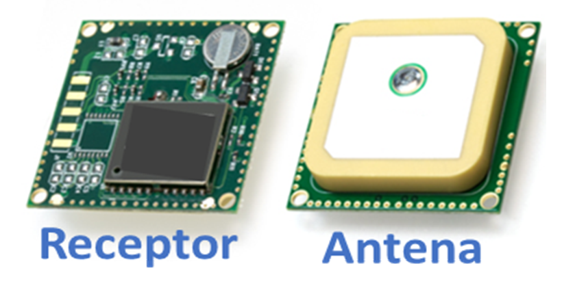
When we have to face incorporating location services into our new device, basically we will have to foresee the installation of an antenna and its corresponding receiver as shown in the following image. In this article we are going to explain the basic principles of operation of GNSS signal reception and how the type of antenna that is chosen can influence the final performance of the system. Finally, we will finish by describing additional performance improvement systems (augmentation systems) that will allow the positioning module to have higher performance.
Operation Frequency
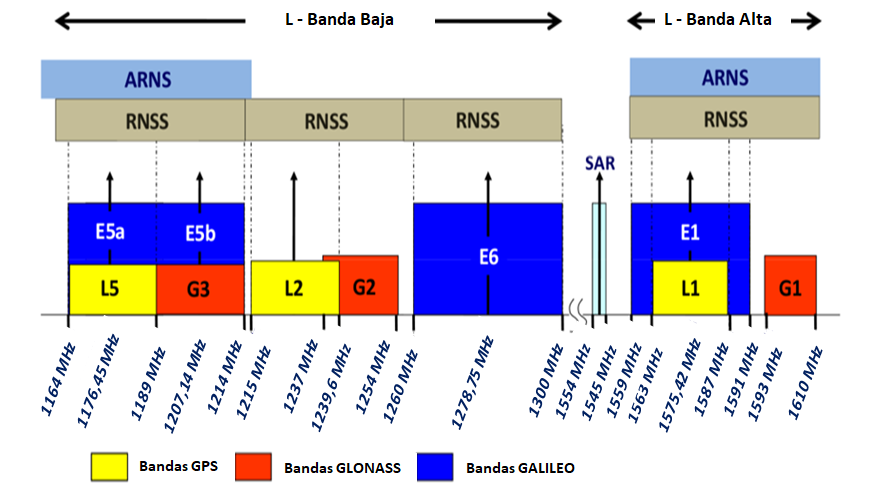
The carriers of the global positioning system are in the L band (1-2 GHz) which includes different bands and constellations of satellites. Currently the 3 constellations with the highest number of satellites are the GPS of the United States of America, GLONASS Russian navigation system and GALILEO European navigation system.
Although the constellation of GPS satellites in the L1 band (@ 1,575.42 MHz) continues to be the majority in use in all positioning applications, the appearance of multi-frequency and multi-constellation receivers, allows to improve the precision performance of the receivers. This has made the range of GNSS antennas on the market much greater and their selection depending on the application we are looking for more complex. As a starting point, we must always be clear in our receiver for which constellations and bands it is designed (next figure), as well as the precision requirements that we hope to obtain.
Impediandia of Athena (ROE)
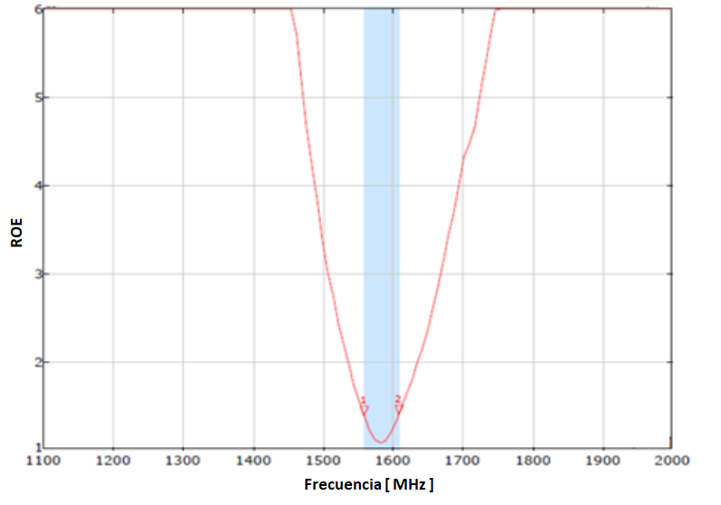
GNSS receivers are designed with an input impedance of 50Ω. On both the GNSS antennas to use also have to be optimized to present an impedance of 50 Ω in the operating bands. The factor that will indicate how well the antenna is adapted to transfer the signal to the reference impedance will be the SWR ( Standing Wave Ratio ), also known in English as VSWR (" Voltage Standing Wave Ratio"). At lower SWR values, better adaptation and greater energy transfer between the antenna and the receiver. Normally for use in GNSS systems, although they are receiving antennas, it is appropriate to expect that the antenna we select has an SWR value <2 in the operating band. This will mean that the antenna will deliver 90% of all the received energy to the receiver (next figure).
Radiation Diagram
We understand the radiation pattern of an antenna as the way in which the energy radiated by the antenna is distributed in space. As shown in the following figure:
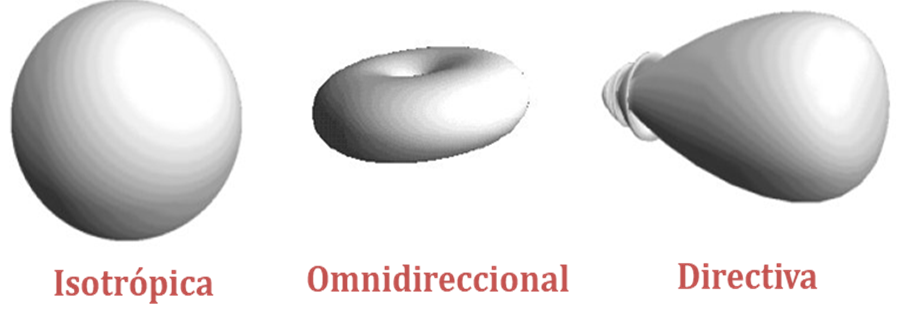
There are 3 basic ways to radiate from an antenna: Isotropic, Omnidirectional, and Directional. It is important to bear in mind that the properties of an antenna are the same in both reception and transmission.
The isotropic is a theoretical form, impossible to carry out at a practical level, but it serves as a reference to define one of the most characteristic parameters of an antenna, such as directivity D ( dBi).
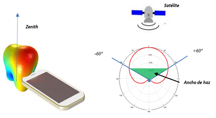
The omnidirectional is one that, at least in one plane, achieves the isotropic characteristic. The "donut" shape of the diagram is a typical example of the radiation pattern of elementary dipoles and antennas, which achieves a 360º equipotential diagram in the horizontal plane . This type of diagram is the one that will interest us for those antennas "on board" or installed in mobile devices with terrestrial communication, where the signal from the transmitter comes from the horizon and the position of the receiver with respect to the transmitter changes over time.
The directive , however, is that way of radiating that focuses all the power in a specific direction of space. In the case of GPS receiving antennas, this will be the desired shape of the radiation pattern, since all the signal we receive comes from the satellites located in the sky (Zenith, highest point in the sky relative to the observer) and the best way to optimize the communication of our receiver with the satellites will be obtained with directive radiation diagrams towards the sky. The following figure shows an example of a typical radiation pattern of a GPS antenna.
Polarization
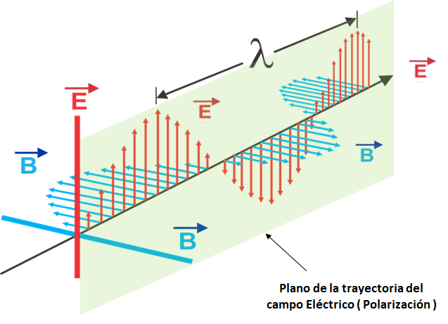
In an electromagnetic wave, both the electric and magnetic fields are oscillating and oriented in space, they are perpendicular to each other and to the direction of propagation of the electromagnetic wave. By convention, the plane of polarization of an electromagnetic wave is defined as the plane that the electric field describes in its path:
The path described by the electric field radiated by the antenna in time can be linear, circular or elliptical. This means that the path that the electric field describes in time can be constant and with a fixed orientation (linear polarization). It can also be moving, following the shape of a circle and with a direction of rotation to the right or to the left (circular polarization), or it can be an elliptical path, understood as a distorted circular polarization:
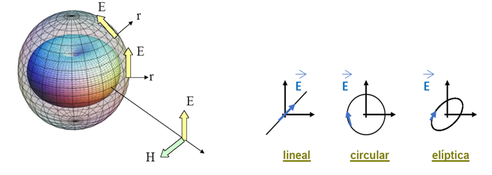
All terrestrial communication systems such as radio, television and telephony use linear polarization transmissions. GNSS systems work with right hand circular polarization (RHCP - " Right Hand Circular Polarization "), avoiding the problem of variable rotation introduced by the layers of the ionosphere on the signals that pass through it. If the transmission were linearly polarized, the signals would reach the receivers with a polarization rotated with respect to the transmission with an unpredictable value, a function of the inclination of the satellite-receiver line and the degree of ionization of the air column crossed.
In the summary of specifications of a GNSS antenna, the parameter that quantifies the quality of the circular polarization of the antenna is the "Axial Ratio" (AR), which is calculated according to the following equation:

With the described equation, from the measurement of the horizontal ( Eph ) and vertical ( Eth ) components radiated by the antenna, the value of AR can be calculated. The higher the level of circular polarization radiated by the antenna, the lower the AR.
GNSS Antenna Types
Although there is a variety of antenna topologies for GNSS applications, according to the bands to be covered and constellations supported, we can classify 3 large groups: patch-type antennas, helix-type antennas and chip or linear antennas.
Antenna Patch . It is the most common type of antenna, flat, built with a ceramic dielectric with a high dielectric constant and an antenna geometry that is approximately rectangular in its upper part:
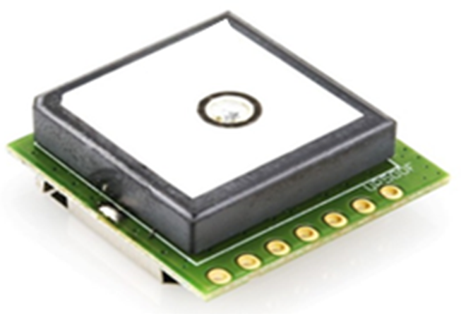
They are ideal for installation on flat surfaces and are low
cost, given their high production.
It is an antenna that can obtain high performance, with a directive radiation pattern, with the maximum radiation in the zenith . You get a gain of 5dB and "Axial Ratio" values less than 3dB in the direction of the maximum. Its performance is highly dependent on the dimensions of the ground plane where it is installed. Normally the minimum required dimensions of the ground plane are 70mm x 70mm. Reducing this ground plane causes a sharp drop in your gain and "Axial Ratio" values.
Another point to take into account is its reduced bandwidth, although it can be optimized for its correct operation for the operating band of the GNSS receiver.
Helix antenna . The actual geometric size of this antenna depends on the dielectric that fills the space between the active parts of the antenna and its propellers:
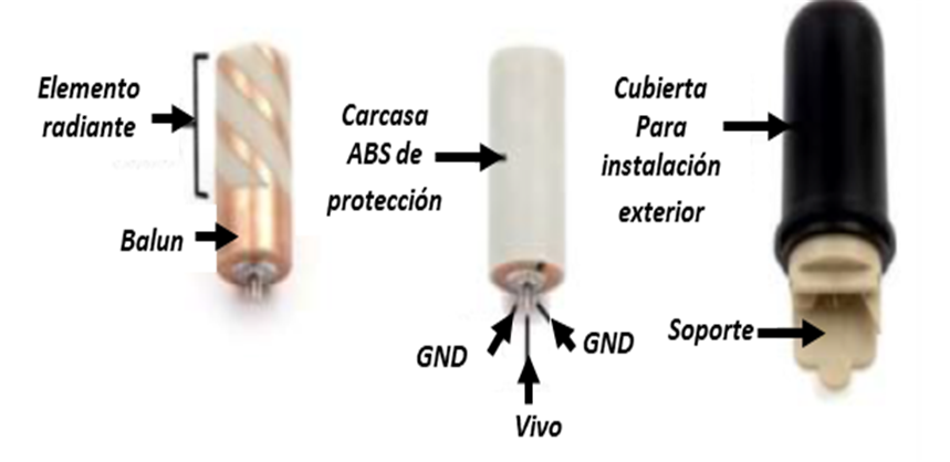
If the antenna has an air core it will be comparatively
large (60mm in length and 45mm in diameter), if the core is ceramic and high
dielectric constant it will result in a much smaller form factor, and as always
your choice will be a compromise between size and performance
In general, with the helical antenna, Gain and Axial Ratio benefits similar to a patch antenna can be obtained, with advantages in bandwidth and beamwidth of the radiation pattern. Its best feature is its independence from the dimensions of the ground plane where it is installed. On the contrary, its dimensions, manufacturing process and cost will always be greater than in the case of the patch antenna. They are robust antennas that demonstrate good positioning accuracy and quality of the received signal.
Chip or linear antenna. These antennas are becoming increasingly popular in GNSS designs due to their low cost and extremely small size (up to 3.2 x 1.6 x 1.1 mm):
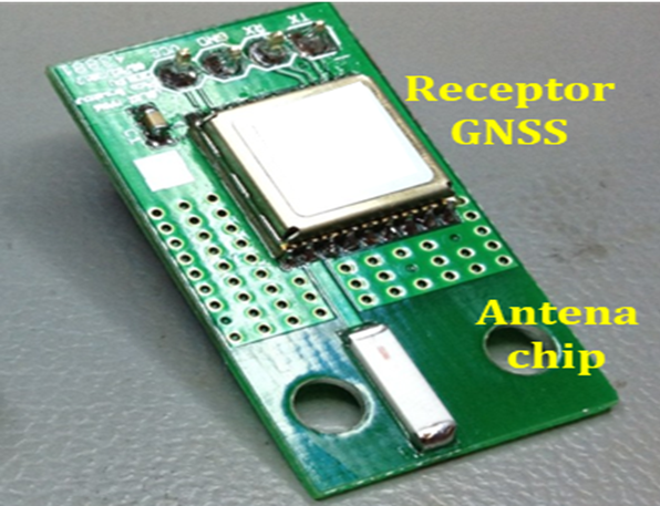
On the contrary, at the level of electrical performance, they differ greatly from patch and helical antennas.
They are antenna designs in linear polarization (infinity AR), which means that they have a loss of 3dB in gain with respect to helical and patch antennas. Its radiation patterns when installed directly in the plane of the printed circuit are omnidirectional, with which the antenna not only radiates towards the zenith , but also presents radiation towards the ground. This loss of directivity, together with the loss of polarization, can result in differences of up to 6 dB in gain between a linear antenna and a patch antenna or the helical antenna.
Due to its small size, a variety of factors influencenin the performance of chip antennas. These factors include the footprint of the antenna on the printed circuit, the size of the ground plane, the distance to the vertices of the printed circuit (5 mm typical) and the mounting of the chip antenna and the GNSS receiver. The antenna's installation footprint on the board can have a major impact on antenna efficiency and therefore GNSS performance, and must therefore be carefully considered in designs. The available ground plane has a significant impact on the performance of a chip antenna. Therefore, not only the size of the chip, but also the ground plane must be considered in the design. For designs with a large enough ground plane, a chip antenna can provide satisfactory GNSS performance. However, in designs with an inadequate ground plane and device arrangement, its performance is insufficient for correct positioning.
The best antenna selection
In the following table we can see a summary of the different options with their advantages and disadvantages.

The choice of the antenna plays a crucial role in the final performance of the receiver and the complete system. Given that GPS for civilian use was not initially considered an application that required high precision, it has led to the development of various methods in recent years to improve its performance, including its functionality in closed areas and areas with difficult coverage. These systems, although not perfect, allow the device to improve its performance, regardless of the selection of the GPS antenna.
Enhanced GPS (Augmentation Systems)
There are several methods of improving GPS performance. Also known as "augmentation systems". Among them, the most used are:
- Differential GPS (DGPS ). Improved positioning accuracy.
- SBAS (" Satellite Based Augmentation System "). Improved positioning accuracy and signal integrity. EGNOS or WASS are examples of implementation in Europe and America respectively.
- Assisted -GPS (A -GPS). Improves reception performance for closed sites, reducing acquisition time to obtain a correct position value.
- Multi-frequency GPS receivers. The performance of GPS receivers is continually being improved, especially with the use of high-sensitivity, dual-frequency receivers.
The use of augmentation systems acquires special relevance when the precision that we expect to obtain is close to 1 m or lower values. We must bear in mind that a GPS system that does not use an augmentation system can have position errors of 1 to 5 m in good signal reception conditions.
Differential GPS (DGPS)
A GPS reference station is located at a known and precisely calibrated position. This reference station determines its position using the available satellites. Taking into account that the position of this reference station is known exactly, the deviation between the measured position and the real position allows us to estimate the positioning error obtained by measuring the signal from each of the satellites used.
These corrections will not be valid for all GPS receivers located close to the reference station within a range of up to 200 km. It is important to understand that the corrections are based on the information sent by the visible satellites in this area and not on the error or deviation obtained at the reference station. In this way, with the data sent by the reference stations, each receiver will be able to improve its precision up to centimeter precision levels:
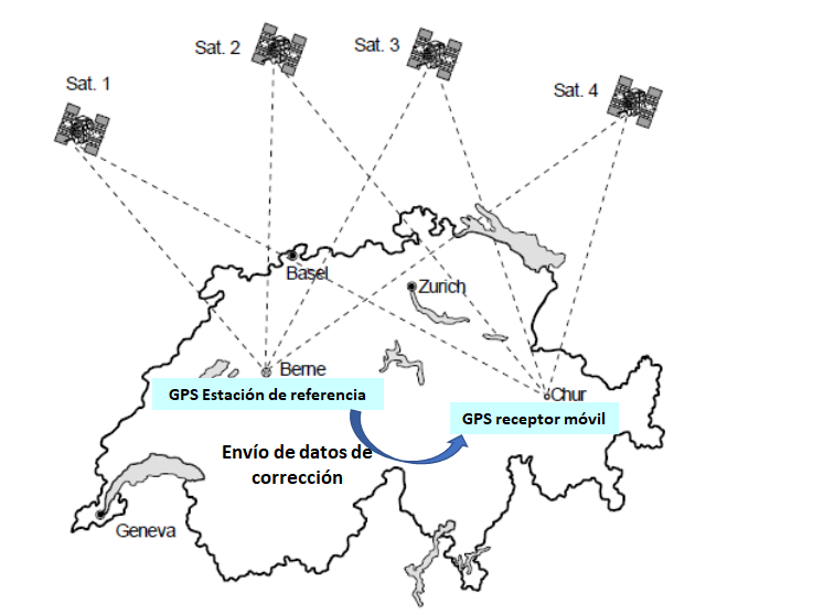
DGPS services collect information from reference stations and transmit it via
radio to mobile receivers. There are a variety of channels available
through which all this correction data is transmitted. Each of these services
uses a specific radio band with its respective advantages and
disadvantages. The following shows a summary of the different radio
transmission systems to send differential corrections, with the range of
frequencies where it operates and a summary of benefits.
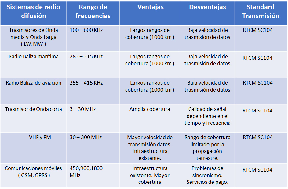
The DGPS reference stations transmit the corrections according to the RTCM SC-104 communications standard, this means that our GPS receiver must incorporate an additional decoder to receive and process the corrections sent. This will raise the cost and complexity of the GPS receiver and is therefore a factor to take into account in the design phase. The final decision to incorporate these systems into our receiver will depend on the final level of precision that we want to obtain.
SBAS (" Satellite based augmentation systems ")
SBAS is a wide coverage augmentation system, where corrections are not based only on measurements from a ground reference station, but a whole network of reference stations in an area or region is used.
The strong point of SBAS systems is that all corrections to improve receiver accuracy are sent by geostationary satellites using the same GPS frequency (L1), following the standard known as RTCA DO-229. This feature allows us to be able to use the same receiver and not have to make major changes to the hardware or the selected antennas in order to have improved precision:
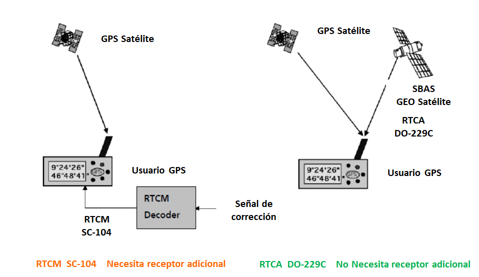
SBAS systems, apart from improving position accuracy, give greater integrity and security to the GPS signals that reach our receiver. Since all SBAS ground stations continuously monitor all satellites and verify whether the information sent by each satellite is valid or not, and thus broadcast it to all receivers.
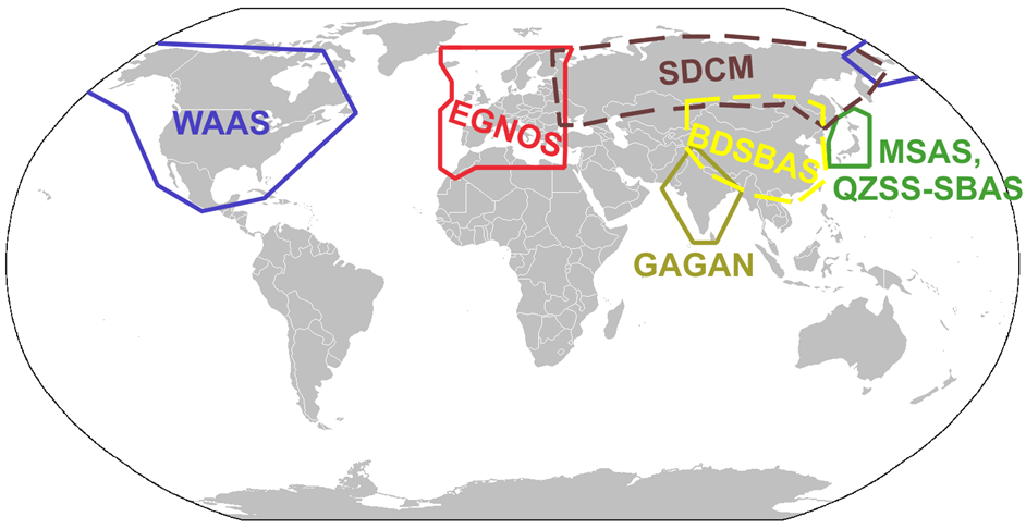
Currently SBAS coverage is quite broad (as shown in the following figure), with 2 major systems: WAAS and EGNOS. WAAS covers the entire North American area (USA, Canada and Mexico) and EGNOS covers the entire Europe area. They are always systems compatible with each other, since they use the same transmission standard (RTCA DO-229C).
Assisted -GPS (A-GPS)
There has been an increase in the number of devices on the market that combine mobile phone functions (GSM, 3G, 4G, etc.) with satellite navigation. It must be assumed that these devices are not always with the GPS active, and thus avoid limiting the life of the battery and its operating time.
As a consequence of the little use of the GPS device, it is likely that there is no information available on the position of the satellites. A GPS receiver normally requires a minimum of 18-36 seconds to be able to get all the orbital information and make a calculation of the first position (this parameter is referred to as the "Time to first Fix : TTFF"). Under difficult reception conditions (eg urban areas with large buildings or spaces that block direct view of the sky), the first position calculation may take minutes to complete. This slow initialization effect is an inherent problem with the GPS system itself and cannot be solved with any improved receiver technology.
In the absence of orbital data, the GPS receiver must carry out a full search in order to find all available satellites, download all the information and calculate the position. The search for all the information is associated with a high consumption of time. Although a constellation of satellites such as GPS can have more than 30 satellites in orbit transmitting information simultaneously, the GPS receiver will need at least 4 satellites to determine our position.
A quick determination of the position and measurement during low signal stretches can be achieved by obtaining orbital information and other information from GPS. This information can be made available via other communication systems, for example via GSM, GPRS, CDMA or UMTS. This application is known as help and is known as " Assisted -GPS" (A-GPS or AGPS). A-GPS is a function or service that uses assistive data to speed up position determination. The GPS receiver receives this help information via mobile phone or over the internet. Help information includes information such as:
- Satellite costellation.
- Accurate orbit data.
- Temporary information.
With the availability of the help information, the GPS receiver can determine the position very quickly, even in situations of poor signal reception:
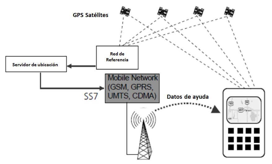
In low signal conditions, this is even the only way to get a
position value. Depending on the complexity of this information, the GPS
startup time can be significantly reduced. Always, the higher the received
signal level, the less time will be required to determine the position.
Multifrequency GPS Receivers
The ionosphere is a layer of the atmosphere located between 60 to 1000 km above the earth. Gas molecules in the ionosphere have a high level of ionization. This ionization is mainly caused by solar radiation. Satellite signals in a vacuum travel at the speed of light, but as they pass through the ionosphere, their speed is reduced and they can no longer be considered to travel at a constant speed.
The level of ionization varies depending on time and location, and is much higher during the day and at the Equator. If the level of ionization is known, this effect could be corrected with models in the receiver. But, since the change in propagation speed is frequent and varies over time, the best way to compensate for it is with the use of dual-frequency GPS receivers.
As shown in the second figure, the navigation systems are already prepared in civil use to operate in dual band. The GPS has the L1 @ 1575 MHz and L2 @ 1227 MHz bands enabled. Therefore, another option to improve the accuracy of our GPS module is to incorporate this type of dual receivers. However, we must bear in mind that the complexity of the antenna and the RF circuit increases, since we will have to select antennas also with double frequency and prepare the receiver input with amplifiers and filters at both frequencies.
CONCLUSIONS
As always, the choice of antenna in a GNSS system is a compromise of three factors: performance, size and cost.
Although chip-type GNSS antennas have become a cheap and small option, their use is not recommended for devices where the navigation function is an essential feature and high positioning accuracy is required.
In applications with high precision and minimal error in the definition of the position, the use of patch and helical antennas is mandatory. In designs where the cost and dimensions are more important, the use of the patch antenna will be the best option, as is the case in the automotive industry.
We have also presented different methods, not dependent on the type of antenna selected, which allow us to improve the performance of the GPS system. From the optimum in performance, as is the case with DGPS systems, to the optimum in cost and less complexity, such as SBAS systems. Using the signal from geostationary satellites in the same band (GPS-L1) we can increase the precision and integrity of the received signal. Currently two of the most widely used SBAS systems are WAAS and EGNOS with coverage in North America and Europe respectively.
As an intermediate solution we have the use of double frequency receivers, which without having to complicate the hardware with as much level as DGPS systems, will allow us to improve the receiver's performance by compensating for propagation errors in the ionosphere.
Leedeo offers you the support and all the necessary advice to develop your GNSS devices. Do not hesitate to contact us >>
Are you interested in our articles about RAMS engineering and Technology?
Sign up for our newsletter and we will keep you informed of the publication of new articles.


